
ULTRASONIC PULSE VELOCITY TEST
Objective and Principle
The ultrasonic pulse is generated by an electro acoustical transducer. When the pulse is induced into the
concrete from a transducer, it undergoes multiple reflections at the boundaries of the different material
phases within the concrete. A complex system of stress waves is developed which includes longitudinal
(compressional), shear (transverse) and surface (Raleigh) waves.
Apparatus Required
The apparatus for ultrasonic pulse velocity measurement shall consist of the following:
a) Electrical pulse generator,
b) Transducer – one pair,
c) Amplifier, and
d) Electronic timing device.
Performance Requirement of Apparatus
The apparatus shall be capable of measuring transit times to an accuracy of ±1 percent over a range of 20
microsecond to 10 millisecond. For this, it is necessary to check the overall performance by making measurements on two standard reference specimens in which the pulse transit times are known accurately. The two reference specimens (usually steel bars) shall have pulse transit times of about 25 microsecond to 100 microsecond respectively; these times being specified by the supplier of the equipment to an accuracy of ±0.2 microsecond. The shorter of the reference specimens shall be used to set the zero for the apparatus and the longer one shall be used to check the accuracy of transit time measurement of the apparatus. The measurement obtained shall not differ from the known value for the reference specimen by more than ±0.5 percent.
Procedure
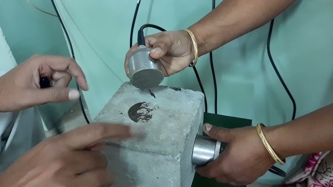
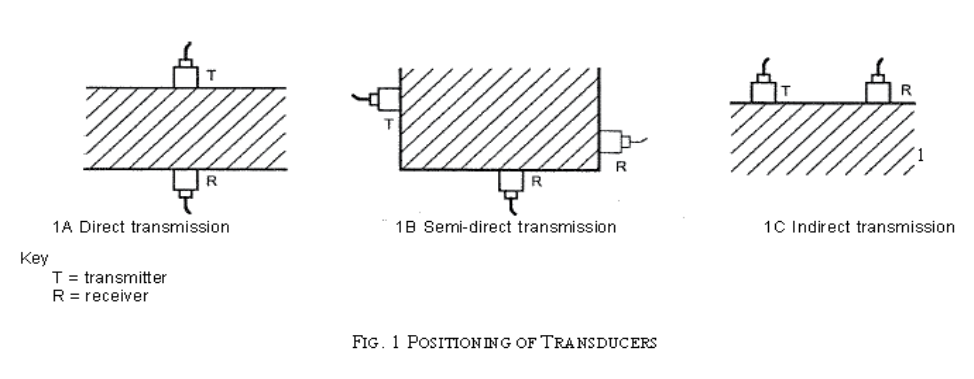
At the point of observation, the concrete surface shall be suitably prepared and any plaster or other coating shall be removed to expose the concrete surface. For this purpose, the use of carborundum stones or grinders may be adopted. However, care shall be taken to avoid any damage to concrete surface or concrete structure. Place the two transducers on opposite faces (direct transmission), or on adjacent faces (semi-direct transmission), or on the same face (indirect or surface transmission).
Although the direction in which the maximum energy is propagated is at right angles to the face of the transmitting transducer, it is possible to detect pulses that have travelled through the concrete in some other direction.
Direct transmission method of ultrasonic pulse velocity measurements is the most efficient method and shall be adopted, if possible.
However, sometimes, it may be necessary to place the transducers on opposite faces but not directly opposite each other. Such arrangements shall be regarded as a semi-direct transmission.
The third method for measurement of ultrasonic pulse velocity is the indirect transmission method. The indirect transmission arrangement is the least sensitive and shall be used when only one face of the concrete is accessible, or when the quality of the surface concrete relative to the overall quality is of interest.
The ultrasonic pulse is produced by the transducer which is held in contact with one surface of the concrete member under test. After traversing a known path length L in the concrete, the pulse of vibrations is converted into an electrical signal by the second transducer held in contact with the other surface of the concrete member and an electronic timing circuit enables the transit time (T) of the pulse to be measured. The pulse velocity (V) is given by: V = L/T.
Surface probing is not as efficient as cross probing, because the signal produced at the receiving transducer has amplitude of only 2 to 3 percent of that produced by cross probing and the test results are greatly influenced by the surface layers of concrete which may have different properties from that of concrete inside the structural member.
The indirect velocity is invariably lower than the direct velocity on the same concrete element. This difference may vary from 5 to 20 percent depending largely on the quality of the concrete under test. For good quality concrete, a difference of about 0.5 km/s may generally be encountered.
To ensure that the ultrasonic pulses generated at the transmitting transducer enters the surface of concrete without resistance, and are then ejected out of the surface, into the receiving transducer, it is essential that there be adequate acoustical coupling between the surface of concrete and face of transducer.
Typical couplants are petroleum jelly, grease, liquid soap and kaolin glycerol paste. In case of very rough concrete surface, it is required to smoothen and level the area where the transducer is to be placed.
Surface probing in general gives lower pulse velocity than in case of cross probing and depending on number of parameters, the difference could be of the order of about 0.5 km/s. In view of this, it is recommended that, in surface probing method the pulse velocity may be increased by 0.5 km/s, for values > 3.0 km/s.
In view of the inherent variability in the test results, sufficient number of readings are taken by dividing the entire structure in suitable grid markings of 300 × 300 mm or even smaller. Each junction point of the grid becomes a point of observation.
Larger grid spacing up to maximum 500 × 500 mm may be adopted for general overall assessment of larger structures having uniform cross-section showing no signs of distress.
Factors Influencing Test Results
There are various factors which influence pulse velocity measurements, such as,
a) surface condition and moisture content of concrete;
b) path length, shape and size of concrete member;
c) temperature of concrete;
d) stress to which the structure is subjected;
e) reinforcing bars;
f) contact between the transducer and concrete;
g) cracks and voids.
Velocity criteria for concrete quality grading
For concrete ( < M25 ) | ||
Sr. No. | Pulse Velocity ( km / sec ) | Concrete Quality Grading |
1. | Above 4.50 | Excellent |
2. | 3.50 to 4.50 | Good |
3. | Below 3.50 | Doubtful* |
For concrete ( > M25 ) | ||
1. | Above 4.50 | Excellent |
2. | 3.50 to 4.50 | Good |
3. | Below 3.50 | Doubtful* |
Our Other Services
- Rebound Hammer
- Ultrasonic Pulse Velocity
- Half Cell Potentials
- Concrete Core
- Carbonation
- Cover Meter Survey
- Pile Integrity Test
- Pile Dynamic Test
- Bridge Load Test
- Slab Load Test
- Cross Hole Sonic Test
- In-Situ Metallography (Replica)
- Portable Hardness Test (Rebound & UCI Method)
- Expert Metallurgy Consultant For Site
- Pressure Vessel Inspection & Maintenance
- Condition Assessment
- Remaining Life Assessment
- Fitness For Service
- Pipeline Inspection & Maintenance
- Tank Inspection & Maintenance
- IBR/Non IBR Fabrication
- Structural Health Assessment / Structure Audit
- Reactor Inspection As Per Factory Act
